Here we go.
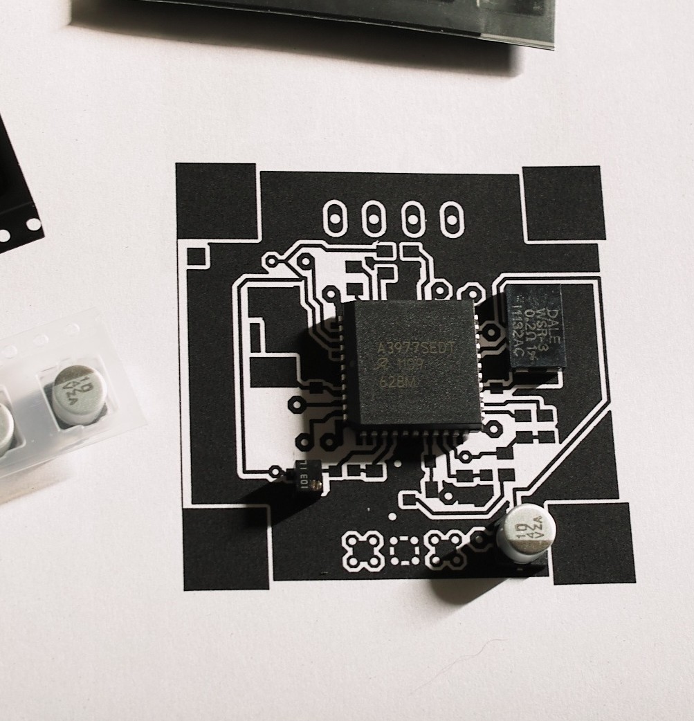
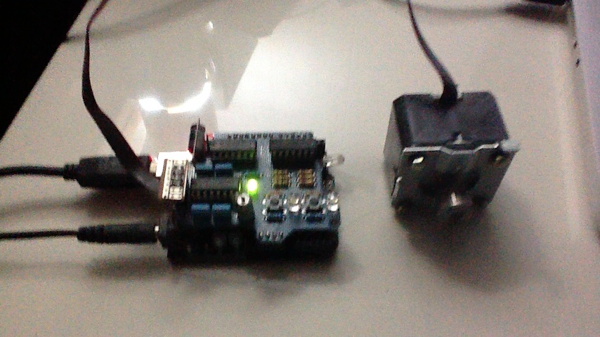
I’m planning to build an X-Y table to allow me to drill printed circuits, from designs I’ve prototyped with an Arduino and created circuit designs for using CadSoft Eagle. It’s basically a small metal slab, about a sixth of a dinner table size, that will slide left and right, forward and backward, very very precisely, under computer control. I’d clamp a printed circuit board to it, and use my notebook to control it and a small drill, to poke holes in the board for later component soldering.
Now, I’m basically a programmer with some units in mechanical engineering that I didn’t see through. There’s a terrible lot that I don’t know about machine design, component sizing, power transmission, tolerancing – but I do know which of these dogeared and dusty University textbooks on my deskshould contain low level details, if I need them. Also, there’s a wealth of information on machinists’ websites that contain ideas that we can cobble together to synthesize a workable design. All that, plus a bachelor’s wherewithal with his weekends and some spare cash, we’re going to go design and build this thing.
Constraints
I live in Mandaluyong City, Manila – full stop. That’s it right there. This is not a Maker Faire friendly city – at least not for the type that can’t be bothered to take a 50-minute commute and walk to go 8 kilometers and visit merchandise shops in the Binondo area. Insane import tariff schedules, and a weak domestic hobbyist market for basic electromechanical components, mean getting hold of anything more complex than prebuilt Arduino boards and common discrete ICs is going to be very tedious – or expensive, if you decide to go take the Radio Shack route. Purchasing a simple ball thread screw and nut online will set you back anywhere between PhP 4,700 to well over 20K – which can be most of a technepreneur’s monthly paycheck.
So there’s going to be some engineering tradeoffs that will hit hard, and early in the design phase. Forget about using 8020 aluminum extrusions for your X-Y table frame – nobody stocks those. You’ll have to use raw metal stock – bars, rods, and simpler, generic extrusions – to impart stiffness and rigidity to your design. Much of the control electronics will need to be built using through-hole soldered components – nobody runs a PCB fab house for hire who’ll run a few boards for your project, as everyone uses imported photosensitive copper-clad FR4 boards. Any small shops that do PCB photolithography in Mandaluyong, Caloocan, Makati, Paranaque or Marikina cities aren’t advertising that. Forget about SMD pick and place machines – you’ll be using tweezers and a lens to put tiny chip resistors and capacitors, and a fine-tipped soldering iron.
That said, the hunting and thinking and working with your hands is just so much fun.
We’ll tackle the project in two huge chunks, and just break those chunks down as we go along.
Step zero is identifying the problem we want to solve:
- Build a motor-controlled, 2-axis milling table using the maximal amount of locally-sourced raw stock and parts, that will permit drilling, milling, and possibly routing operations on printed circuit boards made of copper-clad fiberglass-reinforced epoxy laminate.
Dafuq?
If you’ve seen a pen plotter in action as it draws even just a monochrome floor plan or machine design, you’ve probably also thought – man, that is beautiful. It simply moves a pen along two axes, and triggers pen plunge and withdraw at exactly the right places to, well, draw a thousand words. Pictures of buildings or cars or a Mandelbrot set window, directed by a computer. That pen plotter is your basic 2-axis table, with a spindle that holds a pen (or set of pens), instead of a machine tool or metal/plastic spray head; the third axis of movement, being constrained to raised/lowered to discrete positions, makes it a 2.5-axis table. A three-axis table would permit continuous motion in the third (also ‘z’) direction.
(Hm. Come to think of it, designing this table as a three-axis build might be useful for solving our own problem, as we could plunge a drill bit fast, and just sloooooow down in the last few millimeters or so before making a controlled drill cut. So heck, why not. The rotational degree of freedom in the spindle drill or milling head makes it a 4-axis table, as the spindle drill velocity will no doubt need to be controlled in continuous increments as well, to adjust to cutting conditions and material properties.)
In addition to drilling holes precisely (to within 1/1000 of a drill hole diameter, or better, in both the X and Y directions), we’ll also want the capability to perform routing and milling operations using this table. Typically, a hobbyist circuit design will be small – a few dozen traces, possibly twice as many holes – and so the circuit board will not occupy a whole precut plate. The etched circuit board need to be trimmed to it’s final dimensions. It would be useful to be able to switch between drilling and routing, where the tool bit is made to cut “sideways”, instead of down into the board. The spindle head must be made capable of bearing significant sideways load, up to the buckling strength of the bit.
How about Z-axis precision? Precision costs: A solenoid is cheaper than a ball threaded screw. There are ways to energize a spring-loaded solenoid electromagnet to control acceleration that are fairly inexpensive (by control of current), but achieving accurate positioning with just current control is not so easy, without going into more analog electronics than I’m comfortable getting into. So, we refine the problem details a little further: We need to drill clear through a piece of laminated fiberglass and a few mils of copper that’s about 1/16th of an inch thick, with no real need to punch accurately to an intermediate depth. So we’ll consider controlling depth of cut via solenoid current, limited by mechanical travel stops, and perhaps use a spring-loaded plunger to pull the spindle up when the maximum travel limit has been reached. The lower plunge depth limit can be sensed with a simple contact switch, and is an attractive alternative to achieving [costly] full, three-axis motion precision.
How about transforming rotary motion to linear motion in the other two axes: What are the options?
A slider linkage would be pretty inexpensive. This might use a DC servomotor with position encoders to tell our circuits how far the driving crank is along its’ arc, from which we can compute the absolute position of the sliding link (which gives us the table position). This won’t give us constant accuracy along the plane of travel, though, unless we only use a small portion of the travel path as our working path (in the vicinity of 45° +/- 15 degrees, say). Or we make the crank arm pretty long, and size up the motor accordingly.
Somebody could probably synthesize a straight line path with a 4-bar mechanism. We don’t really care about intermediate inertia forces, as the table will typically be stopped during a plunge cut – when drilling. But this precludes a simple position control algorithm, (which we’ll obtain after synthesis of the straight line path), as we apparently need to control velocity and torque (cutting edge forces) consistently during routing cuts. This velocity constraint imposes an additional path generation constraint that we can transform into a fixed motor speed limit input varying by material, or make into a continuous-valued speed control parameter. I suspect this is possible, stepper motors are said to exhibit large torque driving capability at slow stepping speed. If we can’t synthesize a path generator with closely spaced, discrete stepping points, we’ll almost certainly see jams, bit breakage, or oscillation while a side cutter is running. The shift from point to point on the cutting cylinder would represent tiny jumps in tooth tangential velocity as the stepper is rotated through small discrete angles. This means that we’d need to use a reduction drive and/or microstepping. Interesting.
Then there are timing belts and chain drives, with or without a reduction gear (or gearbox) on each of the steppers; ball screw and nut linear drive with rigid coupling to the axis stepper; rack and pinion drive (with the rack fixed rigidly to the workpiece stage); a conveyor roller (which eliminates the rack and uses friction contact between the workpiece stage and a stepper-driven roller). All these methods are direct drive methods that don’t require pneumatics, for which we won’t need to get into hydraulic drive and the requisite pumps and tubing. We’ll get into those another day.


