Taking a paper prototype to places it really can’t go. This is just a test of placement – the 1-1 size layout simply serves to verify that our parts will rest correctly on the pads.
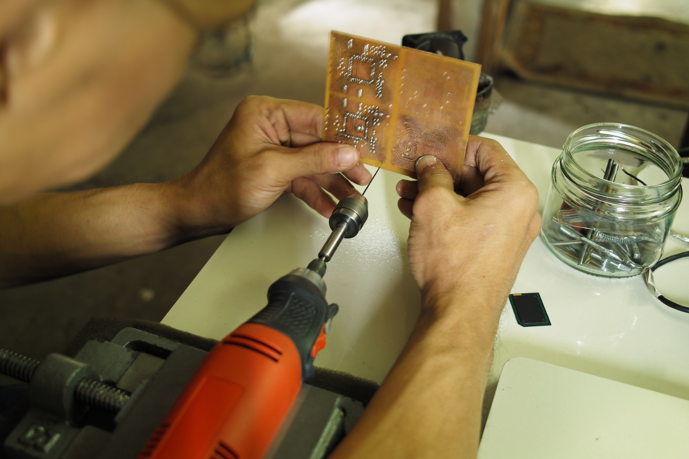
The circuit layout was done in Cadsoft Eagle, with circuit traces that are at minimum 0.5mm wide. It took several days of tweaking the schematic and the layout to ensure that this board could be assembled at all: The screw terminal block (for the motor) and pin headers (for the Arduino) needed to have solder pads all on one side of the board. Any vias would have to be hand-soldered after oven reflow, using snippets of copper wire.
Now to get back to work – etching this over the weekend, after I buy a small oven toaster and thermometer.