It is the day. Today is the day when we finally assemble the first of three motor controllers. Rather than ruin a perfectly well-etched board, we’ll experiment with a vise-mounted, handheld power tool to drill 0.8mm vias into our test board. The test board is a reject from a previous expose-and-etch attempt that had uneven trace widths.
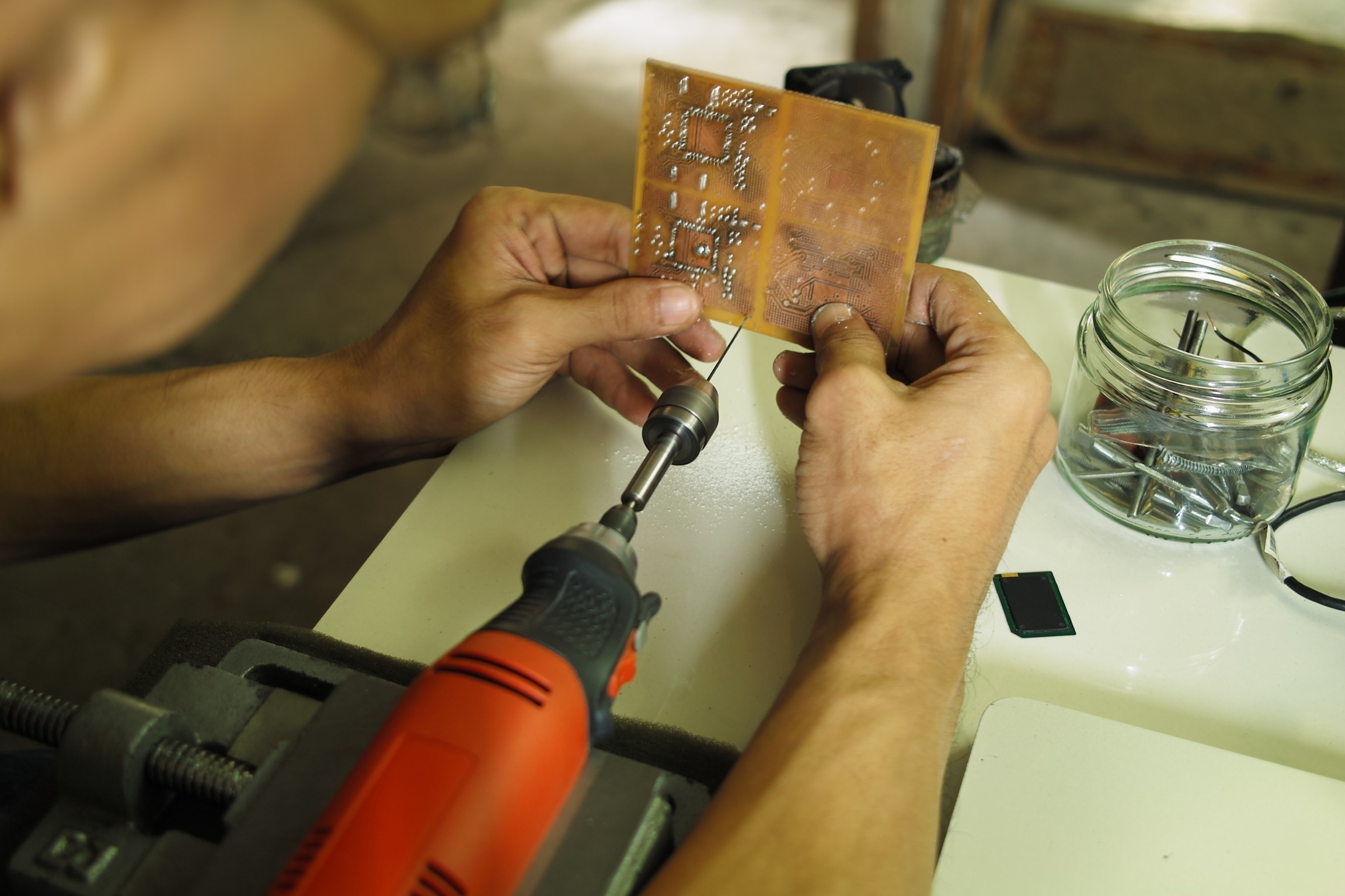
One of the first things one would notice is that this long, thin carbide drill bit tends to flex disconcertingly, threatening to break. That, plus the tendency of the tiny chisel tip to “walk” (a bit like a coin spun on its edge on a hard desktop) makes for inaccurate hole placement. When the tip finally bites into the fiberglass epoxy surface, it may be displaced a good fraction of a millimeter, which ruins the matching copper feature on the other side of the board.
There’s only one remedy for this, which is to reduce the flexure of the bit. Since we can’t make it stiffer (it’s a cemented carbide bit which probably won’t like being heat treated), we’ll break it someplace on it’s fluted length, and mount the remaining tipped part into the hand tool chuck.
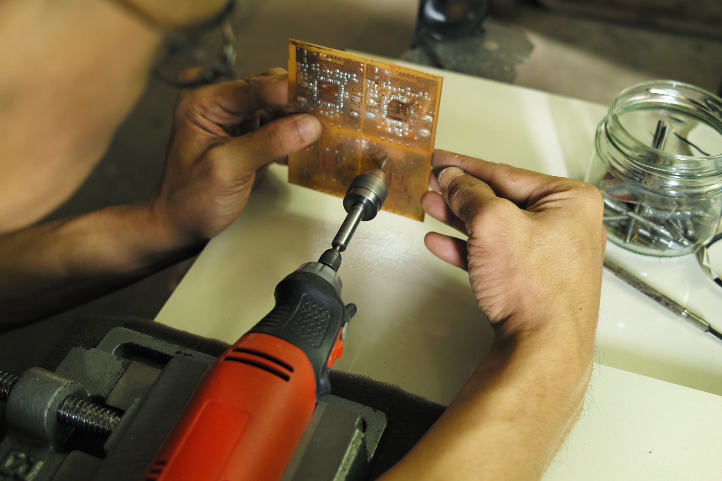
This is much, much better: There is no longer any noticeable flexure in the bit, and we’re able to position the spinning bit and drill holes fairly accurately. The “walking” deflection imparted by the bit can be felt as the board bucks slightly in the hand, so that the board needs to be held rigidly against the drill bit tip. This will become fatiguing for runs of more than ten or fifteen of these small boards. Marking small dimples in the fiberglass board at the center of each drilling position will aid accurate hole placement and reduce fatigue.
Now this tells us that the spindle chuck of our final CNC frame needs to maintain very high rigidity – deflecting less than a hundredth of a millimeter at the maximum deflecting force of about a hundred kilograms weight. Shaft deflection in the spindle motor needs to be held to similar levels of precision – this can be done by fixing pairs of fairly large, high-speed, axial thrust bearings at each end of the motor shaft. Drilling holes by hand like this would also be simplified by using a fixture frame to hold the board perpendicular to the drill axis.
We’ve unmounted the drill chuck here, mounting a 0.6 mm bit, and used it as a handheld center bit to mark hole centers, as a prelude to actual drilling. The idea here is to drill first, and mount components next. We may yet botch the drilling operation, and it will save us money to drill first before mounting and soldering parts, rather than do it the other way around.
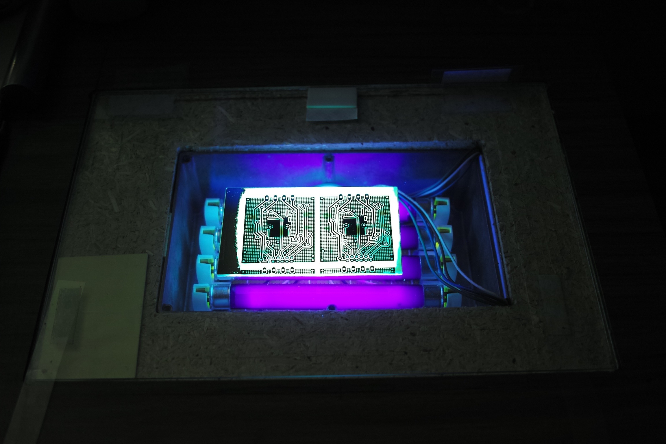
One curious thing about fiberglass-reinforced epoxy is how it flouresces under UV. This property could come in handy for inspection, except that the procedure would require UV-safe eye protection, and I don’t trust retail shops to sell real UVA blocking eyewear. It sure looks cool, though.
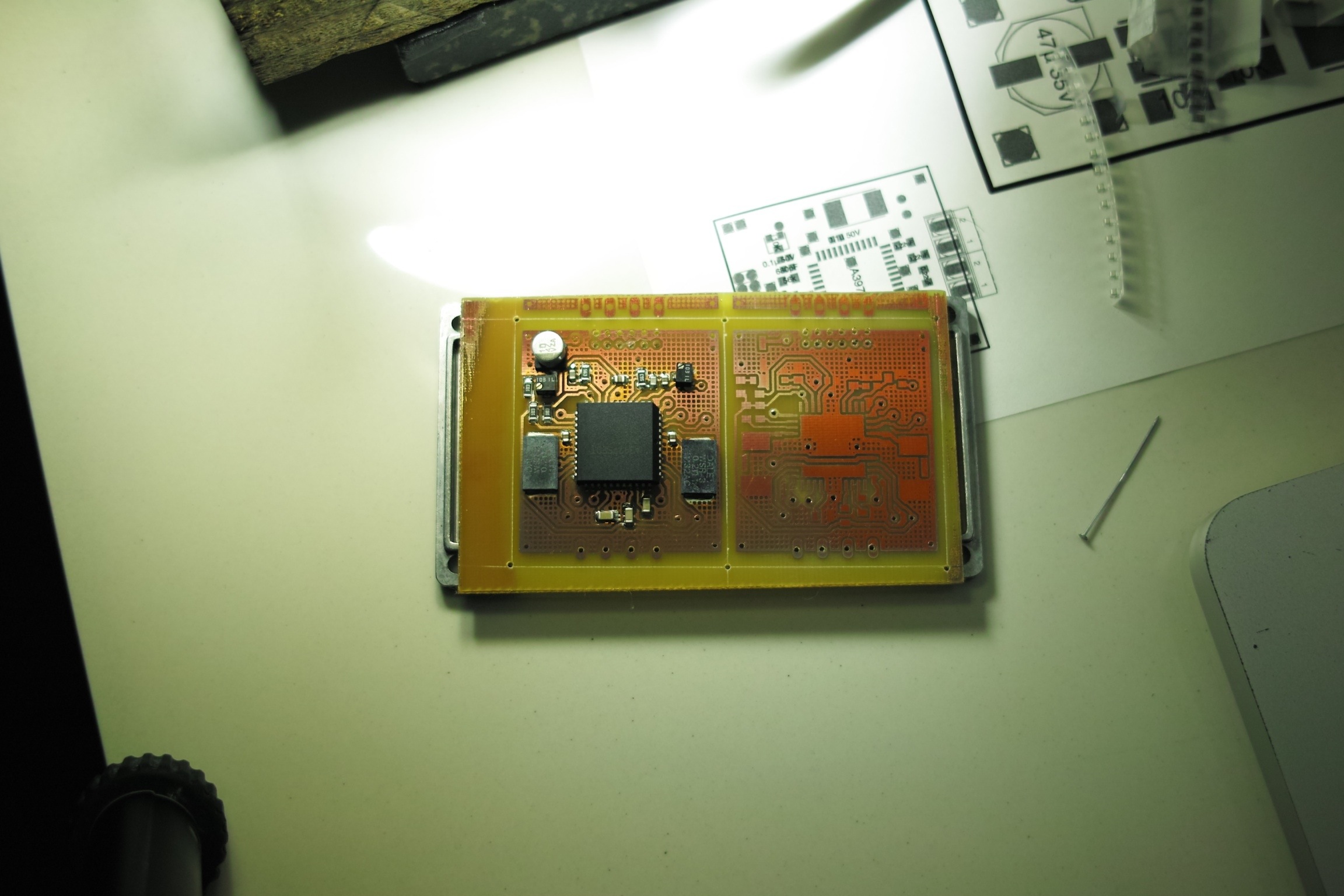
Voila! I became too engrossed with watching a five-minute timer, and peering through our house oven toaster’s grimy glass window to catch the moment of solder fusion, and so neglected to capture pictures of the reflow process (there’ll be a chance to take those shots with the next board we put together). Notice the oxidation film that turned the pristine copper surfaces a shade of not-quite iridiscent orange.
I’m worried that the five-minute reflow was too long a time in the oven. Having followed advice on the Web to maintain reflow temperature at 30 seconds TAL (time above liquidus), I was pretty surprised to see my clock run to 5 minutes 17 seconds, and hurriedly withdrew the board at the 30-second mark. I won’t be surprised if this board fails, though.
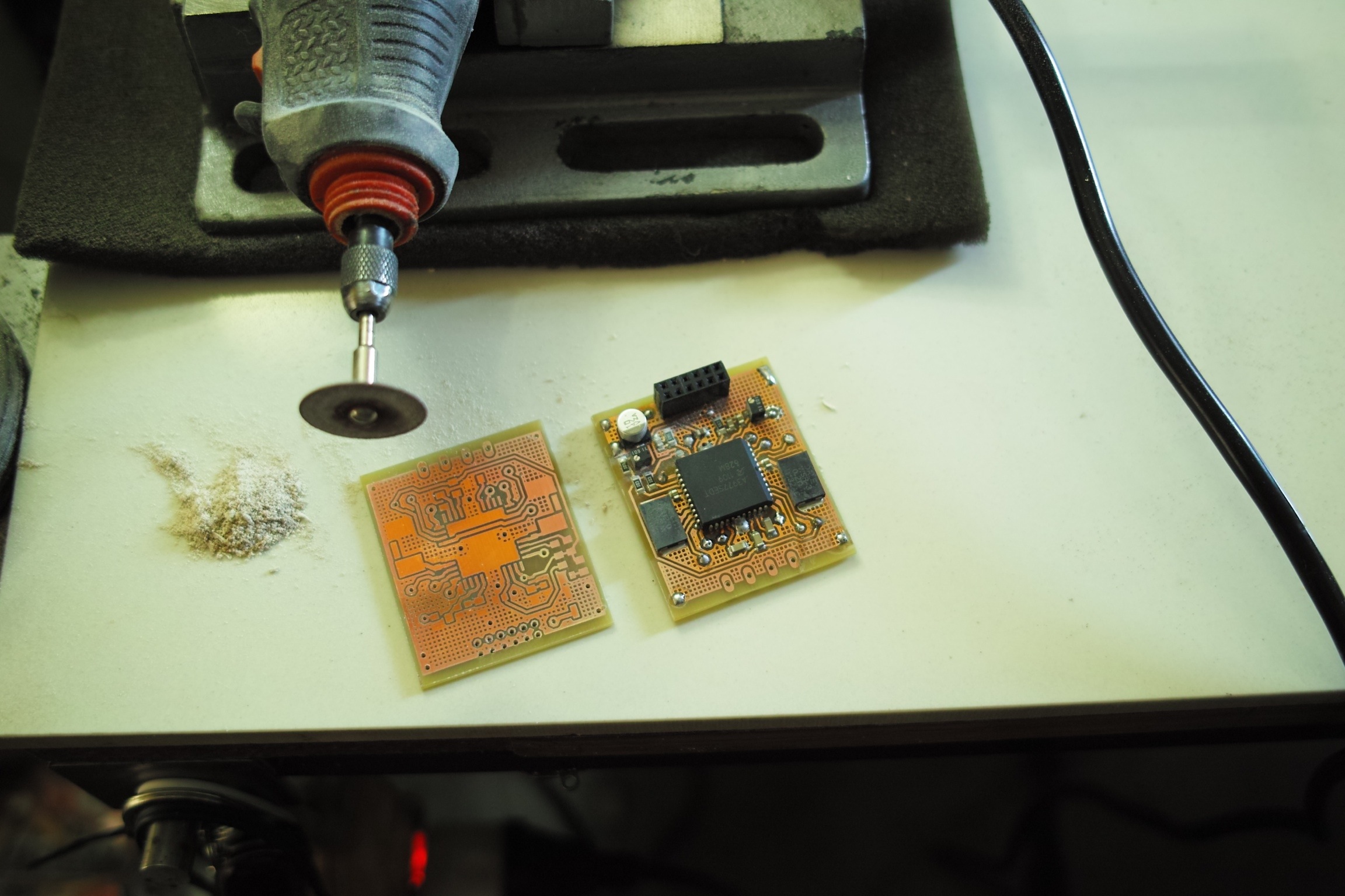
Dicing. The board has been trimmed using the cutting disc, shown. The trick here is to guide the board underneath the fixed disc so that it travels in a straight line along the cutting plane. This is another of the operations that will need to be modified on a milling table, probably using a routing bit.
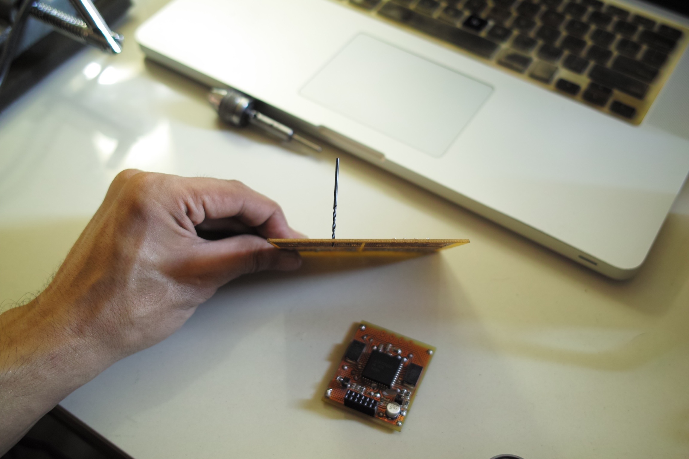
This is another of those problems that a CNC drilling machine will help to solve: Perpendicularity error. This angular displacement of the drill bit is an annoyance that is partly remedied by creating larger copper pads on the opposing face of the circuit board plate.
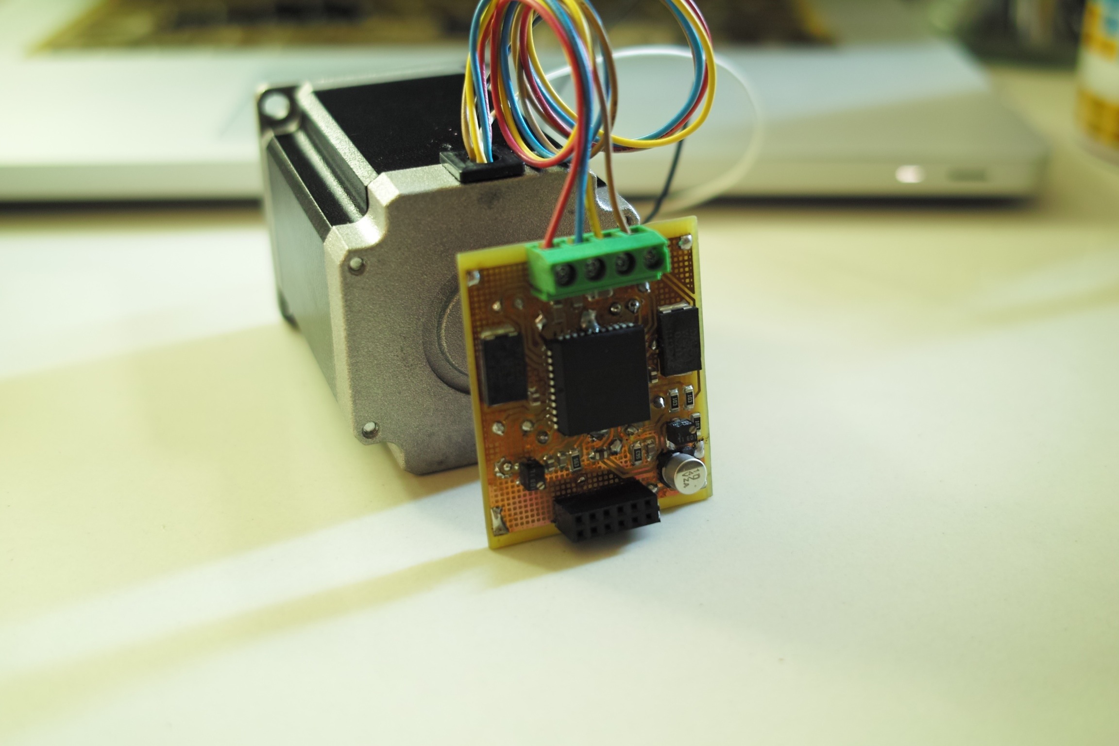
Part 1 completed. We’ve constructed the board, shown here attached to our stepper motor. Next, we’ll do electrical testing and calibration. The board is designed with a pair of multiturn trimmer resistors to control the microstepping current waveform, which we’ll need to adjust without benefit of a test bench – we’ll calibrate the board by making adjustments that yield the lowest temperature rise in the driver chip, and the least noise in the stepper motor.
We’ll write test routines to test bidirectional stepping, and then stepping with a sinusoidal position input. Tonight we wire this up to an ATX power supply and an Arduino to drive the A3977 STEP, ENABLE and DIR pins. If this turns out OK, we’ll begin to adapt a G-code intepreter, and assemble another Allegro driver-based board using one of their TSSOP chips.
Quick Update (20 October 2012): It works!

After a false start where I’d burned out the first prototype board by shorting the motor drive power line VBB and an adjacent pin (with the driver board energized with a 12V PC ATX power supply), I’ve discovered some interesting things:
1) The eighth step mode “loses” steps when trying to drive this 8.5V, 8.5Ω, 17W motor from a 12V power supply. The shaft seems to jump by as much as 10 degrees, at random angular positions. No amount of adjustment of the percent fast decay or blank time potentiometers eliminates the stutter I’m hearing from the motor. See, the A3977 is able to drive motors in “full step” mode (1.8° per pulse on the STEP line, on this Hurst stepper), half step, quarter step, and eighth step mode, and the ability to rotate the shaft 0.225 degree each step translates to 3mm / 1600 = 0.0018 millimeter / step positioning accuracy (assuming zero backlash in the ball screw nut, zero axial play in the motor shaft, and so on). The problem might simply be one of
a) that just twelve volts isn’t a high enough potential difference to cause a full reversal of current through the motor’s windings (the Hurst motor torque curves are given at a 2.0A, 24V, rather than 12V); and/or
b) electrical noise that’s causing my Arduino to hiccup pulses instead of sending a constant 200µsec period (5 kHz, which is well under the 500 kHz rating for the A3977 STEP line input); or
c) an incorrect choice of 0.2Ω for the current sense resistance (which I don’t fully understand how it would affect the way the A3977 “chops” current being sent through the motor. The spec sheet indicates 0.5 ohms, and that a lower, non-zero value would be permissible as well. Must read the spec some more.)
I’ll try to run the board in full- and half-step modes today, still using just this 12V supply, and add a sufficient amount of capacitance to both the A3977 and Arduino logic supply lines to smooth any current draw spikes (the Arduino runs happily off 500mA, and the A3977 seems to require as little as – whoa – 12mA, when . That’s right, 12 milliamps.)
WIth a supply of 12V, neither the chip nor the motor become noticeably warmer after two hours of continuous unidirectional running.
2) We’ll want to take advantage of full and half-step modes to obtain high-speed positioning. We won’t pull the MS1 and MS2 lines high to force eighth step mode, and instead connect them directly to our microcontroller. This gives us an additional design degree of freedom, and will permit us to send the platform to a “home” position as fast as the microcontroller can allow. Using full-step mode with this motor that steps 1.8 degrees per pulse means that 20000 pulses / second can move a 3mm lead ball screw nut 30cm/second, about as fast as a dot matrix printer printhead).
Update #2 (20 October 2012, 7:27pm MNL): Driving at 15V eliminates stutters.
Driving the A3977 using 15V seems to do the trick: No more stuttering in 1/8th step mode, and at the pulse rate the Arduino is able to provide (a bit under 5kHz is my guess), the motor spins at 29 revs per 10 seconds, or 174 rpm. That would translate to a linear velocity of 8.7mm / sec with a ball screw of 3mm lead. Not bad.